C.2.3
List of parts for 1 cooker Ls and for 1 Lw each
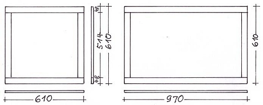
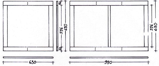
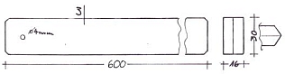
Parts for one Box frame
48 mm wide
|
| Dimension mm |
Ls |
Lw |
Total |
| 514 x 48 |
2 |
2 |
4 |
| 610 x 93 |
1 (1/2) |
|
1 (1/2) |
| 610 x 48 |
1 |
|
1 |
| 610 x 93 |
|
1 (1/2) |
1 (1/2) |
| 970 x 48 |
|
1 |
1 |
| Total: |
4 |
4 |
8 |
|
Parts for one Box frame
52 mm wide
|
| Dimension mm |
Ls |
Lw |
Total |
| 516 x 52 |
2 |
2 |
4 |
| |
|
|
|
| 630 x 52 |
2 |
|
2 |
| |
|
|
|
| 990 x 52 |
|
2 |
2 |
| Total: |
4 |
4 |
8 |
|
|
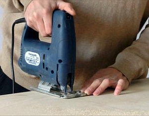
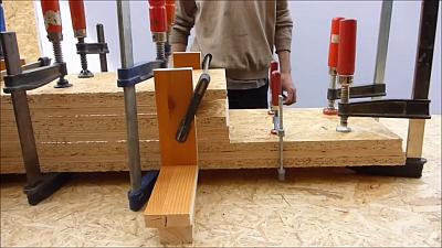
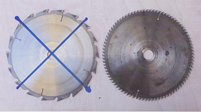
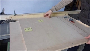
Note concerning the circular saw used:
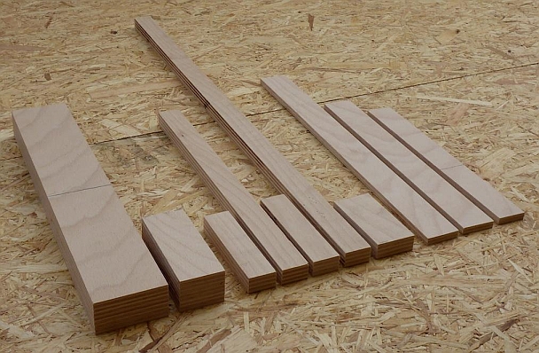
Unfortunately, only a very old circular saw was available when shooting the videos for Appendix C. However, the saw is fully functional and the cut parts are very precise.
C.2.4
Cutting the components of the frame from 8 or 15 (16)mm plywood
C.2.4.1
Preliminary note
If possible cut the parts of the wooden frame from an absolutely straight 15mm plywood board in longitudinal direction of the grain
Should this not be available, make a 16mm board by gluing two 8 mm parts together. For details see Sec. C.2.4.3
|
C.2.4.2
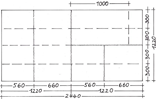
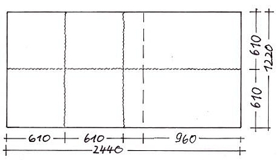
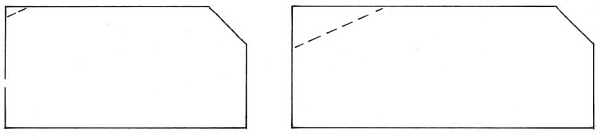
Cutting plan for the wooden frame from a plywood board (8 or 15 mm)
The adjacent fig. is a suggestion how to divide the big board with a circular saw and a jigsaw. All parts lie in the direction of the grain. The suggestion is based on the internationally customary board size of 2440 x 1220mm.
Other dimensions of the boards require a different layout. Take care to have the grain always in the longitudinal direction of the parts
The dimensions in the example given, allow a precise cutting to measurement at the fence of the circular saw after a rough cut with the hand saw or the jigsaw
Legend:
Undulated line: use padsaw
Dashed line: use circular saw
|
|
| 1 |
0:00 |
Mark the lines for sawing first |
| 2 |
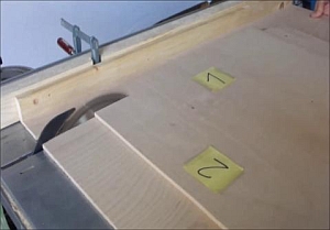
0:05 |
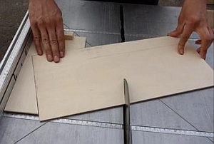
Cut the plywood board along the middle line in two with a jigsaw. Then cut strips 560mm and 660mm wide.
When dividing the plywood board with the jigsaw, place it on top of a robust large working surface (Chipboard). Lift and support the sawing area high enough so that the blade can move freely.
|
| |
|
Cut the sheets to a width of 300mm on the circular saw
Remarks:
- The 8mm boards, which need to be glued in pairs, should not be too wide. Otherwise they cannot be pressed adequately when gluing them together.
- 15mm boards can be cut as wide as the longitudinal fence of the circular saw allows for
- The frame parts should not be cut from the entire width of the plate. Large parts are too bulky and get quickly stuck
|
|
 |
C.2.4.3
Gluing together of two 8mm boards to produce a 16mm board
This section is relevant only, if completely flat 15 or 16 mm plywood is not available. The different colour of the text indicates that the section can be disregarded otherwise.
|
|
C.2.4.3.2
Preparing the gluing
|
|
| 1 |
0:00 |
Arrange pairs of 8mm boards warped in opposite directions. When glued together they will become completely flat |
| 2 |
0:08 |
Mark each pair to avoid confusion |
3
|
0:19 |
See next paragraph |
|
|
One time only tasks:
| |
|
Making a glue spatula |
| |
- |
Cut a ca. 10 cm2 board of thin plywood. Mark one edge every 10mm. (no Video Clip) |
| |
- |
Fix a stop next to the saw blade so that the cuts become some 2 mm deep only. (No Video Clip) |
| 3 |
0:19 |
(Part of Clip C-3) Mark the cut board every 10mm |
|
|
| |
|
Cutting plates of Chipboard for gluing (no Video Clip) |
| |
- |
Cut four parts from a straight sheet of ca. 20mm chipboard:
- two boards 990 x 300 mm
- two boards 630 x 300 mm
|
| |
|
Making angle brackets for gluing (no Video Clip) |
| |
- |
Cut 8 pieces of 200 mm length from a batten 8cm wide and screw them together as angle brackets.
(see Clip C.4, 3 01:38.)
|
|
|
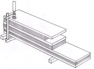
C.2.4.3.3
Gluing the 8 mm plates together
| 1 |
0:00 |
Apply wood glue just to one part of a pair. (After use, clean the spatula with water and a brush, and let it dry.) |
| 2 |
0:33 |
Stack the plates in pairs in between the chipboard plates |
| 3 |
1:38 |
Place the angle brackets from both sides |
| 4 |
1:47 |
Use clamps to align the stack from the sides |
| 5 |
2:24 |
Use clamps to press the stack from top
Hint: After applying the glue there will only be 5 to 10 minutes before the glue sets. The maximum time depends on temperature and humidity. Do not stack more plates than you can process within this time. It might be a good idea to spread the glue at more than one desks simultaneously |
|
|
| 1 |
0:00 |
After approx. 1 hour remove the clamps |
| 2 |
0:21 |
Scrape the glue (not completely hardened)from the straight side which will later be set against the fence of the circular saw |
|
|
| 1 |
0:00 |
Wait at least ca. 3 hours before you trim one long and one short edge. The scraped edge lies against the fence, which is positioned for the correct width |
| 2 |
0:43 |
Make a rectangular cut using the rectangular guide |
|
|
C.2.4.4
Cutting the frame parts out of the (glued) 16 mm or 15 mm plates
From here the instructions apply for 15 and for 16mm plywood.
15mm boards need a trimming cut along one side just as described for the glued 16mm parts in the previous clip.
See the piece list at C.2.3 to find out how many frame parts you must cut. |
 |
| |
- |
Trim parts of the 15mm plywood at one end as shown before with the 16mm parts. (No video clip) |
| 1 |
0:00 |
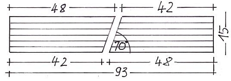
Cut a board with a length of 1m into strips 93mm wide |
| 2 |
0:29 |
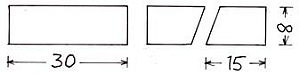
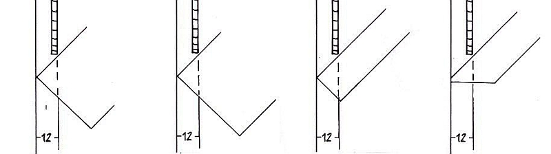
Saw a test specimen of the same width at 70° exactly along the middle. The 93mm strip is cut in two frame parts in the same way |
| 3 |
0:43 |
Saw the 93 mm exactly longitudinally along the middle |
| 4 |
1:20 |
Cut fitting long panels into strips, 48mm wide |
| 5 |
2:05 |
Cut sufficient long panels into strips 52mm wide |
| |
- |
Adjust the cross fence exactly to the different frame part lengths and cut all strip pieces to length. (No video clip) |
|
|
C.2.4.5
Drilling the parts for the glass frame and gluing the frames
C.2.4.5.1
Drilling vent holes through the front and rear parts of the glass frame
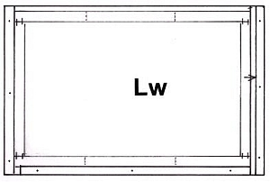
The front and rear parts of the glass frame get approx. 6mm vent holes, one each for the Ls and two each for the Lw. This will prevent the glass from cracking when heated rapidly. The holes are drilled before gluing the frames.
|
|
| 1 |
0:00 |
Fix positioning Jig C1 on the table of the drill stand. The tip of the drill must exactly hit the marked spot. |
| 2 |
0:03 |
Place the glass frame parts for the Ls on one side |
| 3 |
0:21 |
Place the glass frame parts for the Lw on both sides |
|
|
C.2.4.5.2
Gluing the box frame and the glass frame
Take care to join the wooden frames at exact right angles and avoid any skewness. By means of Jig C2, this will be an easy job. |
 |
| 1 |
0:00 |
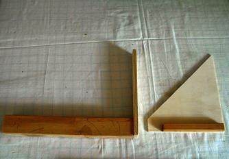
All components of the box frames at a glance |
| 2 |
0:04 |
All components of the box frames at a glance |
| 3 |
0:08 |
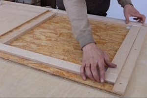
Parts of the box frame laid out for gluing |
| 4 |
0:12 |
Parts of the glass frame arranged for gluing |
| 5 |
0:16 |
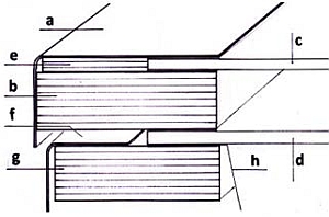
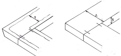
The rear parts of the Ls and the Lw box frames with their 70° angle |
| 6 |
0:20 |
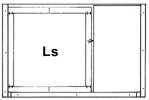
Position the frame components for the Ls on gluing Jig C1. (No video clip) Apply glue to the face sides of the side of the parts only and place them between the front and rear frame parts on both sides. |
| 7 |
0:48 |
The gluing aid is suitable for the Ls and the Lw. For gluing the Ls frames, a 360 mm wide plywood panel is inserted on one side |
| 8 |
0:51 |
Wipe off the extruded glue and connect the corners with staples: They sit on both edges; so they will be hidden later by the flanges of the outer and the inner box. Flatten the staples to prevent them from protruding |
| 9 |
1:21 |
Cautiously turn the frame over. |
| 10 |
1:27 |
Remove the paper residues and glue from the joints before stapling them |
| 11 |
1:39 |
After gluing the frames, stack them crosswise on a perfectly plane base for drying (at least for half a day)
(No Video Clip) |
|
 |
C.2.4.5.3
Sanding and painting the wooden frames
|
|
| 1 |
0:00 |
First is shown how sandpaper is professionally divided into usable parts. Never use scissors or knives |
| 2 |
0:25 |
Fold the single parts twice: The sandpaper gets more stability and each side can be fully utilized |
| 3 |
0:59 |
Surfaces are sanded best with a sanding block. When the glue has set finally, sand the glued joints with medium sand paper and dust them with a cloth |
| 1 |
0:00 |
Paint the box frames on the upper side only (1). The rims will be protected by the flanges of the outer and the inner box. A well applicable mixture is: 1/3 acrylic tinting paint, 1/3 wood glue and 1/3 water. |
| 2 |
0:41 |
The glass frame is painted on the inner (2) and the lower side (3). Mix the paint with equal quantities of acrylic tinting paint and water, this time without glue. |
| 3 |
1:55 |
The strip between the two glass panes of the Lw is painted all around. Use the same paint as for the glass frame. (see Sec. C-5.3: Cutting the bar.) |
|
 |
C.3
Building the reflective cover
C.3.1
Preliminary note:
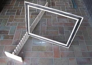
The reflective cover must be cut accurately straight and rectangular. This would be done on a bigger (i.e. more expensive) circular saw. Jig C4 allows to do the job on a smaller machine. To put it to use, a prolongation of the fence of the circular saw has to be made.
|  |
C.3.2
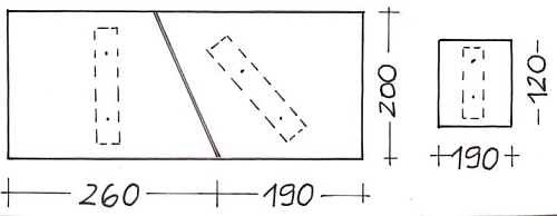
Roughly cut the reflective cover from a big 8 mm plywood board using a Jigsaw
The adjacent picture gives an optional, convenient layout for the cuts. All measures are slightly larger than finally needed.
Cut the board in pieces, similarly as with the frame parts using a jigsaw
|  |
C.3.3
The precise cutting to shape of the reflective cover using cutting Jig C4 for parallel cuts
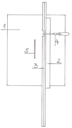
Preparation: Making circular saw stop extension
The adjacent figure shows the table of a small circular saw (1) and the rip fence (3) to be made from two wooden battens.
It is attached to the existing fence (2) with a screw clamp (4). It serves as a guide for Jig C2.
Note: When purchasing a circular saw, make sure that the distance between the circular saw fence (2) and the saw blade (5)
is at least 350 mm. This distance is needed when cutting the plywood panel parts for the wooden frames. (See also Annex C, Chapter C-2.4.2)
| |
- |
For the extended stop, cut two battens that are as straight as possible, approx. 5 mm wide and approx. 1.7 m long. (No video clip) |
| 1 |
0:00 |
Screw the parts of the second ledge onto the continuous one, leaving a recess for the screw clamp. In doing so, compensate for any curvatures of one strip by opposing curvatures of the other strip |
| 2 |
0:25 |
Fix the stop extension to the circular saw stop with a screw clamp |
|  |
C.3.3.1
Making the precise cut for the Ls cover with one or two rough edges:
| 1 |
0:00 |
Cutting aid Jig C4 is to be pushed along the extended fence without jerking or tilting |
| 2 |
0:04 |
Position the extended fence of the saw so that the slit of the Jig fits flush to the saw blade |
| 3 |
0:11 |
Pieces, that have been cut with a jigsaw have rough edges and an overall low precision |
| 4 |
0:29 |
Place the reflective cover with one of its straight edges against the front fence of the jig and fix it with a clamp |
| 5 |
0:51 |
Cut 1: Move the Jig C2 straight along the saws fence. The overlap of the cover plate is cut off precisely |
| 6 |
1:15 |
Cut 2: Fix the cover again and make the second cut |
|
 |
C.3.3.2
Cutting the Ls cover to precision if there is only one even edge:
| 1 |
0:00 |
Place the only even edge against the front fence and clamp the plate |
| 2 |
0:13 |
Before cutting move Jig C2 to a distance of about 10 mm from the saw fence |
| 3 |
0:20 |
Move the fence towards Jig C2 |
| 4 |
0:27 |
Cut off the protruding edge. Due to the extra 10 mm there is enough width to cut the opposing edge straight as well |
| 5 |
0:59 |
Set the fence back to its original position |
| 6 |
1:12 |
Cut edges 2 and 3 straight too as shown in Clip 12 |
| |
C.3.3.3
Making the precise cut for the Lw cover with two uneven edges:
The reflective cover must be cut straight on a long and on a short edge.
| 1 |
0:00 |
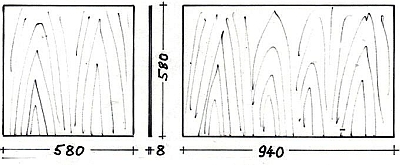
Set a mark at 94 cm near the long straight edge of the cover |
| 2 |
0:12 |
Position the board sideways, matching the edge to be cut exactly to the mark. Clamp the board and cut |
| 3 |
0:51 |
Now turn the plate into the longitudinal direction and cut again |
| |
C.3.3.4
Sanding and painting the reflective cover
The reflective cover must be cut accurately straigt on one long and one short side.
| 1 |
0:00 |
Sand both sides of the reflective cover in direction of the grain using a sanding block and sandpaper with medium grit |
| 2 |
0:13 |
Sand the edges first using coarse and then medium sandpaper |
| 3 |
0:37 |
Round the corners smoothly with the sandpaper folded three times |
| 4 |
0:48 |
Put two wooden strips under the reflective cover, paint the edges and some 2 cm of the inner side. (in the video quickly drying acrylic paint is used) |
| 5 |
1:29 |
Turn the cover and paint the top side brushing first crosswise, then in the direction of the grain |
| |
C.4
Making further wooden parts for the Ls and the Lw
|
|
C.4.1
List of the parts
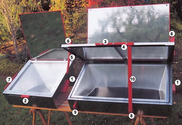
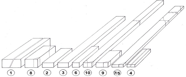
All other wooden parts are numbered. Each of them improves the functionality of the cooker:
| 1 |
|
Cooker handles |
| 2 |
|
Handle of the glass frame of the Ls |
| 3 |
|
Handle of the glass frame of the Lw |
| 4 |
|
Part at the handle for the Lw glass frame |
| 5 |
|
Reflective cover support |
| 6 |
|
Block at the glass frame support |
| 7 |
|
Glass frame support for the Ls |
| 8 |
|
Block for mounting the glass frame support for Lw |
| 9 |
|
Rest for the glass frame support Lw when the cooker is closed |
| 10 |
|
Glass frame support Lw |
|
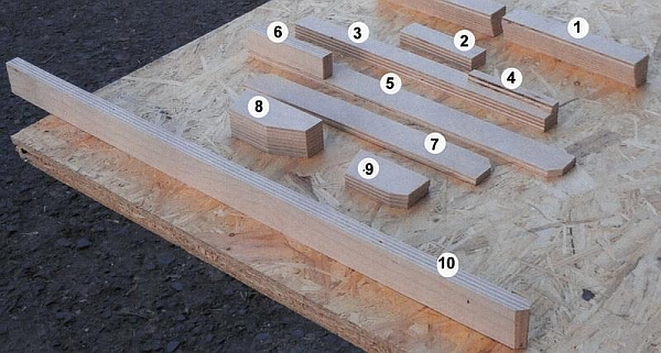 |
| Part 1 |
|
 |
| Part 2 |
|
 |
| Part 3 (with Part 4) |
|
 |
| Part 5 (with Part 6) |
|
 |
| Part 7 |
|
 |
| Parts 8 and 9 |
|
 |
| Part 10 |
|
 |
C.4.2
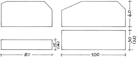
Step 1:
Cutting the basic shapes of the parts (before making oblique cuts)
| |
- |
Glue together boards as needed (No Video Clip)
2x 8 = 16 (or 15 mm)
4x 8 = 32 plywood (or 2x 15 mm)
|
| |
- |
Cut all basic forms precisely (No Video Clip)
|
|  |
C.4.3
Step 2:
Additional cuts
|
 |
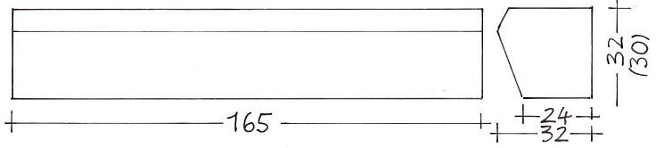
| 1 |
0:00 |
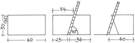
Adjust the saw blade to 70° (see figure). Check that you really cut the block into equal halves by turning the block after
the cut start and starting anew. In case the blade does not exactly match the sawing gap, adjust the guide slightly to fit |
| 2 |
0:20 |
Cut the block into equal halves |
| 3 |
0:24 |
Position the fence to 40 mm and cut again in a 70° angle |
| 4 |
0:31 |
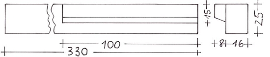
Cut the handles to 165 mm length (+3 mm for the saw cut) |
|
 |
| |
- |
Split part 4 in the same way and then cut lengthwise |
|
 |
Reg. Part: |
5+7 |
8+9 |
10a |
10b |
Some parts need
further cuts |
 |
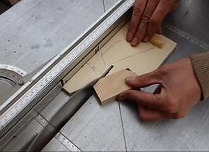
The applied jig consists of two parts.
Jig C5a is only required if the side circular saw fence is to the right of the circular saw: the front,
thick strip is attached to the cross stop. If the circular saw fence is to the left of the saw blade, the part to be cut at an angle is pushed directly along it.
Jig C5b has a 45 degree bevel. With it, the parts to be cut are pushed along the Jig C5a
|
 |
| 1 |
0:00 |
(Part 5) Trim the corners of the reflective cover support for Ls and Lw consecutively at diagonally opposed ends. Use C5 a+b |
| |
- |
(Part 7) Trim the corners of the glass frame support for Ls consecutively - this time the cuts are on the same side. |
| 2 |
0:23 |
(Parts 8 and 9) Cut one lower corner |
| 3 |
0:28 |
(Part 10) cut one end twice to form a rectangular tip |
|
|
For the cutting of the upper corners of parts 8 and 9 use positioning Jig C6.
| 1 |
0:00 |
Position the jig as shown and set the fence against it |
| 2 |
0:13 |
Cut off the upper corner at both parts. (part 9 is 2 cm longer than part 8) |
|
|
 |
C.4.4
Gluing various parts together, sanding and painting all parts
| |
- |
Parts 4 and 3 as well as parts 6 and 5 are glued together. Apply glue to one side only |
|
|
C.4.5
Sanding and painting of all wooden parts
| 1 |
0:00 |
Sand all wooden parts using a sanding block and/or folded sandpaper. Dust off with a dry cloth |
| 2 |
0:43 |
Make yourself a simple appliance to hang the painted parts |
| 3 |
0:47 |
Two wooden sticks tighten the cords |
| |
- |
Set a screw into all parts at a place that will not be visible later. (No Video Clip) |
| 4 |
0:57 |
Paint all parts |
| 5 |
1:52 |
Hang the painted parts on the cords for drying |
| 6 |
1:59 |
Do not wash a brush that you need soon again nor put it into a glass of water but just keep it wet between paper or cling film |
|
|
C.5
Cutting further parts
C.5.1
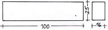
Reinforcing plywood parts for the box handles
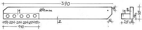
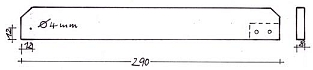
When screwing the handles to the box of the Ls and Lw the metal parts underneath must be reinforced by 4 mm plywood from inside. The same applies to the base of the glass frame support.
Left for the lateral handles of the Lw box
Middle for the lateral handles of the Ls box
Right for the glass frame support of the Lw
|
 |
| |
- |
Cut rectangular plywood panels to the dimensions shown in above Figure. (No video clip) |
| 1 |
0:00 |
Cut two pieces out of one sheet |
| 2 |
0:07 |
Use -Jigs C7 and C8 to adjust the circular saw |
| 3 |
0:20 |
Cut the plate by means of Jig C7 in two parts |
| 4 |
0:37 |
Drill holes in the reinforcement plates using Jig C8: oblique for the Ls and horizontal for the Lw. |
|
 |
C.5.2
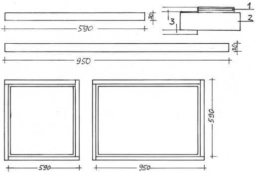
Cutting compensating strips for the glass frame
The glass panes (3), glued with silicone to the wooden glass frame (2), recede 35 mm all around with reference to the frame border.
Compensate this with 4mm plywood strips (1), so that the metal glass frame will be well supported later. (no video)
Number of pieces needed and their lengths:
Ls: 4 pieces 590 mm
Lw: 2 pieces 590 mm
2 pieces 950 mm
|
 |
C.5.3
Central bar between the two glass panes of the Lw glass frame
This bar is cut of 15 or 16 mm plywood. (no Video Clip)
C.5.4
More strips and wedges
Some more strips and wedges will be needed to reinforce the bottom of the inner box.
Their cutting will be explained there. (see
Clip 6.1)
| |