1.1
The metal parts of the LAZOLA - an overview
Important preliminary note:
When planning the layout for cutting the metal parts, those for the outer box and for the glass frame are taken into consideration at the same time.
That is why this overview includes the parts for the box frame, although their assembly will only be described in section 2.
|
 |
1.1.1
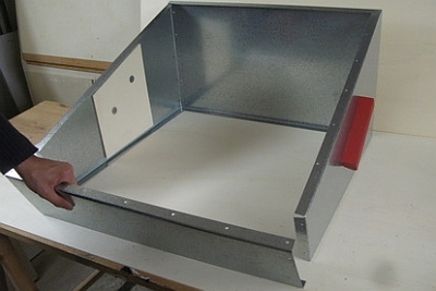
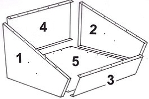
The parts of the outer box
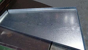
The outer box is made from five zinc coated 0.5 mm sheet metal parts. They will be joined by riveting folded flaps.
The LAZOLA is built in two widths. The LAZOLA standard (Ls) is square. The LAZOLA in double width (Lw) is 360 mm wider; It has the twice the capacity of the Ls.
1.1.2
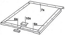
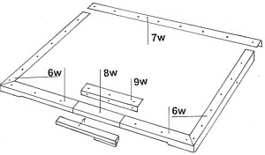
The parts of the metal glass frame
The metal glass frame is made up of three parts: two side parts, which are each cut in one piece with half of the front part (6),
and the rear part (7) (see Clip 7.6).
The LAZOLA can be built in two sizes: the standard cooker (Ls) is square shaped. The LAZOLA with double width
(Lw)is 360 mm wider and has twice the capacity of the Ls.
The side parts of the outer box (1 and 2) are identical in the Ls and the Lw. Parts 3 to 5 are 360 mm longer in the Lw version than in the Ls version.
The construction manual with its video clips and text provides a step-by-step guide for making the LAZOLA. It also conveys innumerable helpful technical hints and advice.
|
|
1.2
Cutting the metal parts parallely
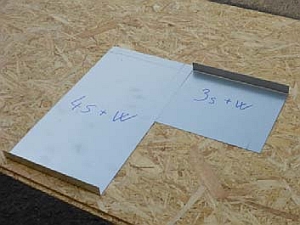
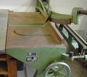
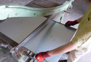
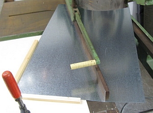
For the cutting of the parts, guillotine shears are needed.
The sheet metal parts are cut best from standard sheet metal plates (1000* x 2000 mm), as most guillotine shears can only cut up to slightly more than 1000 mm.
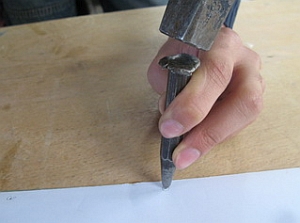
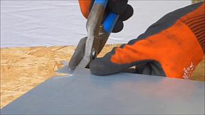
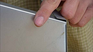
If the metal plates are wider, first cut the plate by hand using tin snips that allow passing through the sheet (the upper model in the picture).
* The length dimension for the frame parts 6w and the corresponding trimming aid in the table are 1005 mm. This is the actual width of many sheet metal plates.
If the parts 6w have to be cut out of larger metal plates, they should also be cut to a width of 1005 mm. Measuring is done by hand.
|
 |
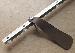
Top: Tin snips for long cuts (plate shears)
Below: Simple tin snips for short cuts only
|
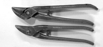 |
Simple tin snips are more precise for short cuts. For long cuts, snips that pass through the sheet without deforming it are necessary. Therefore it is advisable to have both types of tin snips. |
|
All measurements can be found in the illustrations under point 1.2.3. The overview here is just for orientation.
Paper templates are provided for all parts in the original measurements. They convey all necessary instructions on how the parts must be processed.
Jigs
For manufacturing the LAZOLA, many manufacturing aids are used, which make measuring and marking largely superfluous and enable very precise work in general. They are all numbered, e.g. Jig 1.2, which is used in the second place of sect. 1.
|
 |
- Guillotine shears usually have adjustable parallel stops, but here we recommend to use pairs of positioning jigs instead.
They are named Jigs 1.1 (or simply: 1 to 17).
- Since Jigs 1.1 16 are required in different lengths, the complete number has additionally the current number of the jigs, e.g Jigs1.1-1
- Jigs1.1-1 - 9 Are used for cutting the components of the outer box
- Jigs 1.1-10 - 17 Are used for cutting the components of the metal glass frame
- All positioning jigs are aligned in pairs to the right and left of the sheet to be cut:
- If the rest to be cut off is too narrow for clamping, the plate is marked with a positioning jig at an edge and then placed to the transverse stop of the guillotine
|
|
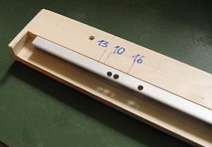
Important note:
As a simpler solution, the different cutting aids have been replaced by only 4 adjustable ones in pairs.
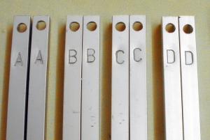
To find the unmarked holes in the respective U-rail, it is applied to a batten Jigs 1.0.
On it the position of all holes is marked in four different colors:
| Rail A: |
|
blue |
| Rail B: |
|
red |
| Rail C: |
|
green |
| Rail D: |
|
black |
Important:
The marks A-D are located at the end of the rails, where the hole for hanging is located.
For selecting the jig, the hole ends of the rails are put on Jig 1.0.
For cutting, this end of the rail abuts the table of the shears.
Regarding the different lengths of the respective jigs see survey in Appendix A 1.3
|
|
| |
|
The provided pairs of positioning jigs cover all occurring widths that need to be cut. They allow for an exact production without using a ruler to measure and mark. |
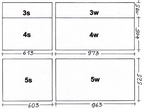
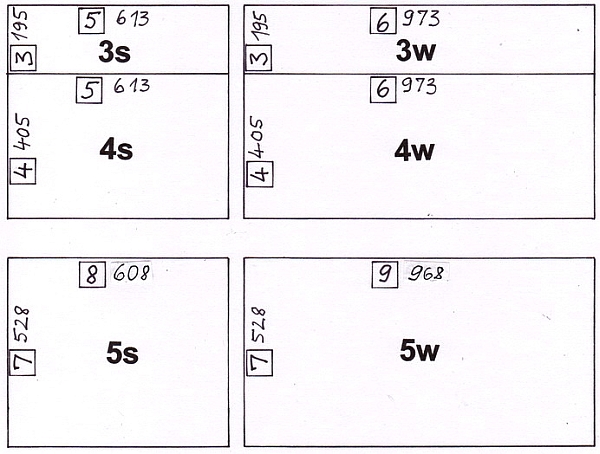
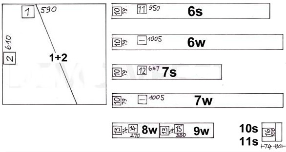
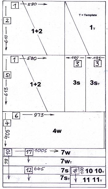
Legend:
- In the adjacent illustration, all positioning jigs (1-16) are represented by numbers in squares which are located where they are used.
E.g. the bottom parts 7s and 7w are cut to 528 mm with the help ofJig 1.1-7 (shortly Jig 7).
- All Jig numbers are set in small squares
- The digits next to the square (e.g., 535) indicate the length of the jig (that is, the dimension of the corresponding cooker part).
|
|
1.3
Planning the cutting
- The clip shows the plan for cutting all the sheets for a Ls and a Lw with minimal waste.
- In the first run, all parts for box and frame are produced twice. The additional parts will replace the paper templates in serial production. They will be used for marking and drilling.
- The adjacent parts list gives an overview of all parts needed.
|
List of parts
for 1 small and 1 wide LAZOLA (Ls +Lw)
and of the metal templates for all parts
|
| Part number |
Quantity of parts |
Quantity of templates |
Number of parts in total |
| 1 and 2 |
4 |
1 |
5 |
| 3s |
1 |
1 |
2 |
| 4s |
1 |
1 |
2 |
| 3w |
1 |
1 |
2 |
| 4w |
1 |
1 |
2 |
| 5s |
1 |
1 |
2 |
| 5w |
1 |
1 |
2 |
| Legend: s: standard; w: wide; L: left side; R: right side |
Section 2 The parts for the glass frame will be cut in Sect. 2 |
| 6s L |
1 |
1 |
2 |
| 6s R |
1 |
1 |
2 |
| 6w L |
1 |
1 |
2 |
| 6w R |
1 |
1 |
2 |
| 7s |
1 |
1 |
2 |
| 7w |
1 |
1 |
2 |
| 8w |
1 |
- |
1 |
| 9w |
1 |
1 |
2 |
| 10s |
1 |
1 |
2 |
| 11*) |
1 |
1 |
2 |
|
|
for an economic distribution the cuts should be planned in advance.
The following hints may serve to avoid waste:
Step 1:
Prepare templates to scale 1:10. There is a master copy in appendix A-4.1 of the construction manual (you will need more than one copy).
Step 2:
Position the model templates (in scale 1:10) as economically as possible onto the model plates (see master copy in appendix A-4.1).
If in doubt, add up all the measurements as given on the "cooker parts", to avoid any mistakes.
|
|
|
Master copy A-4.3 shows one of several possible layouts for all parts needed on three metal sheets. This means all parts for a LAZOLA Ls (standard) and a LAZOLA Lw (double width) - including the templates.
A rule for this layout was to try to position parts of equal dimensions next to each other, so they can be cut in one go.
Have the parts arranged in such a way that parts 1 and 2 can be cut first (see preliminary note in the next section).
|
|
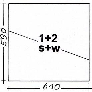
Preliminary remark:
First the metal template T (template) for the side parts 1 + 2 is made. It must be cut out first.
This metal template is required for manufacturing of parts 1 and 2.
The side parts must be made prior to the other parts, as the exact measurements of box parts 3 and 4 depend on them. Depending on the folding bench used, dimensions of the folded side parts can vary slightly.
|
 |
|
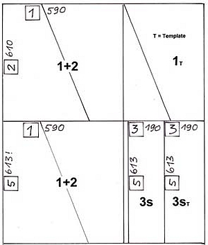
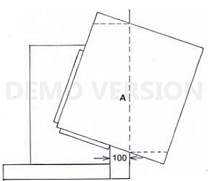
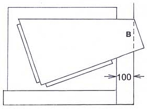
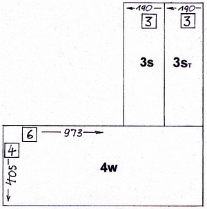
Page 1 of the master copy A-1.2 indicates which positioning aids must be used in order to cut the almost square plates that are to be used for the side panels.
Order of the parallel cuts:
- 1 Use Jigs 2 to cut the full width of the plate.
- 2 For the second cut, use Jigs 5 instead of Jigs 2 to match the length of the parts 3s.
- 3 Cut both parts with Jigs 1. The 410 mm wide remainder is used for the metal template.
- 4 Cuts 4 and 5 are done with Jigs 3 (parts 3s and 3sT)
The skew cuts of parts 1 + 2 are done with a jig at the next point but one. (It does not matter, however, that the lower parts are 613 mm instead of 610 mm. They will be cut correctly by length with Jig 2b).
|
 |
| 1 |
0:00 |
Tape the cut out paper template for parts 1+2 onto the previously cut out metal plate |
| 2 |
0:20 |
Mark the corners using a steel nail
|
| 3 |
1:38 |
Punch the positions for the holes that will later be used for riveting and screwing
|
| 4 |
1:54 |
Punch the holes for the handles of the box too. They are slanted for the Ls, but horizontal for the Lw
|
| 5 |
2:18 |
Now cut the marked template with the guillotine shears
|
Using the metal template to adapt the positioning appliances Jig 1.2a
and Jig 1.2b to the guillotine shears
The positioning appliances Jig 1.2a and Jig 1.2b are used when cutting the diagonal sides of parts 1 + 2
(and the metal template for those parts). Before the jigs can be used, they must be adapted to the particular guillotine shears that are being used.
| 1 |
0:00 |
Put the metal template onto Jig 1.2a and align it so that the short front edge touches the blade of the shears |
| 2 |
0:21 |
Remove the protective film from the double-sided adhesive tape
|
| 3 |
0:29 |
A correcting strip is part Jig 1.2b Use the front stop of the guillotine shears to stick it carefully onto Jig 1.2b
|
| 4 |
0:47 |
Turn the jig upside down and fasten the strip using screws Nr. 6
|
| |
- |
Prepare Jig 1.2a in the same way. (No video Clip)
|
|
 |
| - |
|
Clamp Jig 1.2b 2b to the guillotine shears. (No Video Clip) |
| 1 |
0:00 |
Position the longer side of the plate 1+2 that was cut in section 1.4.1 1 on the stop of Jig 1.2b and cut through the plate.
|
| 2 |
0:15 |
Repeat the procedure with the remaining part of the plate |
| |
- |
Clamp Jig 1.2b to the guillotine shears. (No Video Clip) |
| |
|
Use Jig 1.2a to make the short cuts on both parts
|
|
 |
| 1 |
0:00 |
Cut the already marked corners of the metal template for the parts 1 and 2 exactly with the (simple) metal shears |
| 2 |
0:10 |
Once the metal template is cut, use it to mark the corners of parts 1s+2s and 1w+2w |
| 3 |
1:01 |
Cut out the marked corners precisely |
|
 |
| 1 |
0:00 |
For drilling the holes at the edges of parts 1+2, stack several of them (up to 10) using positioning aid
Jig 1.3. Put the metal template with the holes already marked and punched on top. Fix the stack with a clamp |
| 2 |
0:39 |
The clamp can be an obstacle when drilling. Replace it with a clamp on the opposite side, where no holes have to be drilled |
| 3 |
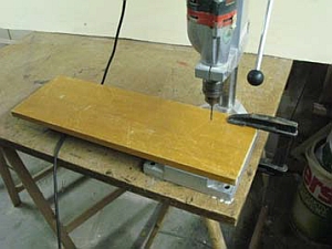
0:49 |
Drill the holes using a (simple) box column drill with its table enlarged with a board. Make sure that the drill is exactly above the punched mark each time.
(From then on the holes in the template will serve as guiding holes.) |
|
 |
| 1 |
0:00 |
Drill holes for the box handles. Those in the Ls and in the Lw have different positions. Stack the parts for the Ls and the Lw separately. Put the metal template on top and clamp the stack*. The template is already marked for the holes for the handle screws of both the Ls and the Lw and for the safety chains on the left cooker side**. Then drill the holes for the Ls.
* Stacking can be made easier by using the holding device Jig 1.3
** To avoid mistakes, it is advisable to cover holes that are not needed with sticky tape |
| 2 |
0:49 |
Label the drilled parts with "Ls" |
| 3 |
1:05 |
Repeat these steps for the Lw
(A better way of labeling is shown in Clip 1.14) |
| |
- |
Drill an additional 4.2 mm hole behind the handle holes on the left part (which was overlooked in the video).
Do this for both the Ls and the Lw. It will hold a safety chain that keeps the glass frame from opening too far. (see Clip 8.13) |
|
 |
Preliminary note:
Usually, a folding bench does not bend plates of varying length with the same angle. To adjust the angle of the bench, test with scrap metal plates that have about the same length as the parts that have to be bent.
| 1 |
0:00 |
Place a scrap metal plate into the folding bench and bend it to 90° |
| 2 |
0:16 |
Check the angle using gauge Jig 1.7 If the angle is wrong, correct the angular stop of the folding bench |
| 3 |
0:25 |
When bending part 1, position it exactly into the folding bench using adjusting aids Jigs 1.4. The upper edge (the one with holes) remains visible. Important: Make sure that the parts are bended in pairs. |
| |
| 1 |
0:00 |
Using folding Jig 1.5 to bend the three other edges. This way all parts are the same size |
| 2 |
0:19 |
Position Jig 1.5 on the side panel so that the front and rear flaps of the plate are equally wide |
| 3 |
0:38 |
When positioning parts 1 and 2, take care that the bending Jig 1.5 is aligned flush with the edge of the folding bench. A short piece of wood can be helpful for this |
|
 |
Preliminary note:
Folding Jig 1.5 does not allow fully bending to 90°. This makes it necessary to complete the bending by hand:
| 1 |
0:00 |
The bending done directly on the folding bench is bent exactly to 90° |
| 2 |
0:07 |
The bends that were done using Jig 1.5 are only bent to about 85° |
| 3 |
0:13 |
Bend these parts using the correcting Jig 6a+b until it stops |
|
 |
|
The labeling done in Clip 1.10 is changed now to better discern the left and right parts (1 and 2) . Do this for both the Ls and the Lw
|
|
1.5.1.2
Determining the width of box part 3
Step 1
| 1 |
0:00 |
Cut two parts, exactly 195 mm long from a roughly 200 mm wide metal sheet, using positioning Jigs 1.1-3. Label them. |
| 2 |
0:20 |
Bend an edge of each test plate to 90° using Jig 1.4 (In the video, Jig 1.4 is erroneously labeled as Jig 1.2) |
|
|
Step 2
| 1 |
0:00 |
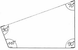
Bend the lower edge of the first test plate to 70°, using a short plywood panel with a width of 160 mm, which is approximately the width of the front edge of side part 1 |
| 2 |
0:31 |
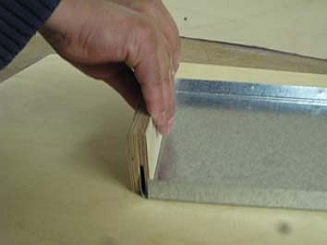
Now place the test plate that was bent on both sides at the front of one of the side parts |
| 3 |
0:49 |
Use a wedge to determine the gap between the test plate and the front part (in the video this gap happens to be 2 mm - but this will differ depending on the folding bench) |
| 4 |
1:00 |
Cut off part of the plywood panel according to the result (here: 2 mm) |
|
 |
Schritt 3
| 1 |
0:00 |
Now bend the second test plate to 70°, this time using the modified plywood panel. Test the fit with the front of the side part |
| 2 |
0:18 |
The second test plate now should have a perfect fit with the side part |
|
|
1.5.1.3
Determining the width of box part 4
The process is the same as shown in Clip 1.16 and Clip 1.17:
| 1 |
0:00 |
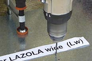
Measure and mark two approx. 200 mm wide sheet metal strips with positioning Jigs 1.1-4
(405 mm = the width of box parts 4s and 4w) - (The plate is too short to place it with both parts of the positioning jig.
That is why it can't be fixed.). |
| 2 |
0:20 |
Put the strip against the lateral stop and cut it at the mark. It is best to place a board (approx. 200 mm wide) between the lateral stop and the plate to be cut. This will aid with a cleaner cut. |
| 3 |
0:23 |
Label the parts |
| 4 |
0:29 |
Bend the edges of both test plates to 70° using Jig 1.41 |
| 5 |
0:41 |
Cut a plywood board to the measurement of the back width of the bent side part (in this case: 361 mm) (no video from cutting) |
| 6 |
1:05 |
The test plate is now folded at both edges. Hold it to the rear of one of the side parts.
Make necessary adjustments to the plywood panel to use it for the second test plate (in the video it
happens by chance to fit perfectly)2 |
|
|
1.5.1.4
Cutting the 3 mm plywood positioning panels used for bending parts 3 and 4
| 1 |
0:00 |
Cut the positioning panel
Jig 1.8a (part of the supplied jigs, but not yet cut to exact measurement) to the determined width (see Clip 1.16 - in the video the measurement was 158 mm). This jig will be used during serial production |
| 2 |
0:14 |
Cut the positioning panel Jig 1.4 to the determined width. As the stop of
the circular saw is not wide enough, the small strip to be cut off is placed against the stop (This is only
possible if the panel has the same width on both sides) |
| 3 |
0:40 |
Label both positioning panels |
|
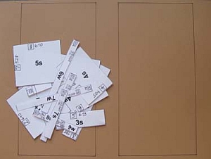
Preliminary note:
The parts from the overview in Appendix A2 that are now needed have been copied here.
All the parts needed are produced twice; the second set will be used as a metal template later.
|
 |
| |
- |
Correct the positioning Jig 1.1-3 and Jig 1.1-4 according to the width that has been found out before. (No video clip) |
| 1 |
0:00 |
Use positioning Jig 1.1-4 and Jig 1.1-4 to cut parts 3s and 4s at the guillotine shears to the correct width |
| 2 |
0:27 |
Label the parts |
| 3 |
0:36 |
Mark the parts 4s and 4w with Jig 1.1-6 in length. Attach a wooden plate approx.
200 mm wide to the guillotine shears' lateral fence and cut the parts |
|
|
|
Use trimming aid Jigs 1.1-3 (Teil 3s und 3w) to cut part 3s (and
part 3w) in the same way. Cut to a width of 195 mm, then cut the parts with the help of
Jig 1.1-5 (and Jig 1.1-6) to their appropriate length. Mark the parts 3s and 3w. (no video clip)
|
|
| (brown: One time tasks) |
| |
- |
Cut the parts 5s and 5w in the known way by means of Jigs 1.1-7 to
1.1-9.
Simultaneously cut 1 plate 5s and 5w each for metal templates. (no video clip) |
| 1 |
0:00 |
Tape the paper template on the cut out bottom parts, that will later serve as metal stencils |
| 2 |
0:12 |
Punch mark the holes through the paper stencil |
| 3 |
0:22 |
Drill 3.5 mm holes |
| 4 |
0:37 |
Label the drilled plates 5s and 5w as drilling templates |
| 5 |
0:44 |
Fix the drilled templates on top of one or more cut plates on one or several (later in the serial production) bottom plates |
| 6 |
1:09 |
Use the already drilled metal template as drilling guide and drill 3,5 mm holes in the plates below |
| |
- |
Store the drilled parts until needed in sect. 5.2 |
|
|
1.5.4.1
One time only task:
Prepare the metal templates of box parts 3 and 4 for drilling
Use the paper templates for parts 3s+w and 4s+w, to punch mark all holes for rivets and screws on the metal templates
|
|
| 1 |
0:00 |
Clamp the template for 3s onto the corresponding plate. Then drill 3.5 mm holes |
| 2 |
0:40 |
Do the same for the 3w |
| 3 |
1:18 |
Important: When marking and drilling the holes on the 3w do not forget the holes for the glass
frame support and its rest |
| |
- |
Drill parts 4s and 4w in the same way as 3s and 3w. (no video clip) |
|
 |
| 1 |
0:00 |
Use adjusting aids Jigs 1.4 to bend parts 4s and 4w
to 70° at the long edge with the holes in it (in the clip, the jig is falsely labeled as Jig 1.2 instead
of Jig 1.4) |
| 2 |
0:28 |
Use positioning Jigs 1.4 to fold parts 3s and 3w to 90° at the long edge with the holes in it |
| 3 |
0:47 |
Use positioning Jig 1.8b to bend part 4s and 4w to 90° on the lower side |
| 4 |
1:10 |
Use positioning Jig 1.8a to bend parts 3s and 3w to 110° on the lower side |
|
|