3.1
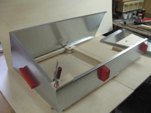
Mounting the box handles
Fix the handles to the sides of the outer box.
Their exact position is determined by the mounting
device Jig 3.1 The handles of the Ls are slanted,
the handles of the Lw are horizontal.
|
 |
| 1 |
0:00 |
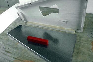
The block that is set next to the conical handle prevents the handle
from shifting. |
| 2 |
0:19 |
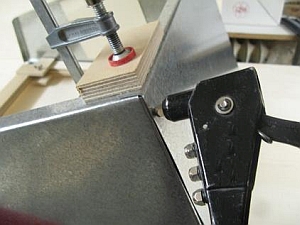
Place one of the approx. 4 mm plywood panels that were cut in appendix C
(see Clip 22) on top of the plate so that the pre-drilled holes are exactly
on top of each other. Apply silicone to the underside of the panel
before fixing it. |
| 3 |
0:56 |
Drill 2.5mm holes for the screws. |
| 4 |
1:20 |
Fix the handle with screws Nr. 7*) and washers Nr. 14 |
| 5 |
1:51 |
Remove the completed part from the jig. |
*) Note:
- The numbers of all small parts are in green.
- The list of all small parts can be found in appendix B.2
|
| 
|
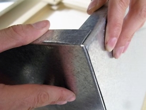
3.2
Jointing the Box Parts with Pop Rivets
The walls of the outer box are jointed with pop rivets No. 1 verbunden.
The holes in the rear and front part are already drilled. The holes in the underlying flanges of the side panels are drilled through the existing holes to make them fit exactly.
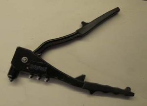
Use riveting pliers with various inserts, suitable for rivets of varying diameters **).
(see also Clip 3.9)
Note: Rivets and hole sizes are matched, so make sure to use the fitting size.
|
|
| 1 |
0:00 |
Insert the pop rivet and compress it using the riveting pliers. |
| 2 |
0:10 |
Rivet No. 1 has a diameter of 3 mm. The hole in the upper plate has a diameter of 3.5 mm and the one in the
lower plate has a diameter of 3.2 mm. The compressed rivet fastens the lower plate. If both holes were 3.5 mm in diameter, the rivet would not be able to grip the lower plate.
Hint: If the lower hole is too wide, a 3 mm washer No. 11 can be used.
|
|
|
|
3.3
Riveting together the rear wall and the side parts
In order to fit the frame parts together, they are clamped into the holding device Jig 3.3
|
|
| 1 |
0:00 |
Insert the first side part and gently fix it with the wing nuts. |
| 2 |
0:27 |
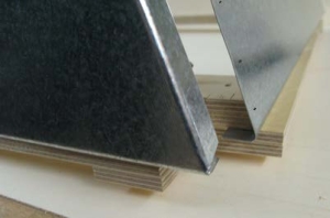
Place the rear wall. The upper flange of the rear wall is now under the flange of the side part.
(When the cooker is finished, the upper flange of the rear wall will be on top.) |
| 3 |
0:31 |
Precisely align the rear wall: The upper flange of the rear wall is now under the upper flange of the side part.
The bottom flanges are on top and are lying in whichever way fits best. The rear wall is receding about 3 mm on the sides.
|
| 4 |
0:41 |
Fix the lower side of the aligned corner with the wing nut on the jig and fix the upper part with a small clamp. |
| 5 |
1:05 |
Drill 3.2 mm holes into the rear flange of the side part. |
| 6 |
1:19 |
Rivet the rear wall using pop rivets Nr. 1. |
| 7 |
2:37 |
Fix the second side part in the same way. |
|
|
3.4
Fixing the front part of the box
|
|
| 1 |
0:00 |
Align the front part in a similar way to the other parts and drill holes with 3.2 mm |
| 2 |
0:51 |
Do not rivet the front part, but instead fix it temporarily with woodscrews Nr. 8
instead as it must be taken off again. As the screws do not have a thread all the way up to the head, use a washer Nr. 12.
|
| 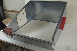 |
3.5
Removing the box from the holding device |
|
| 1 |
0:00 |
Remove the screws from the front part. |
| 2 |
0:12 |
Loosen the wing nuts. |
| 3 |
0:28 |
Remove the front part. |
| 4 |
0:34 |
Remove the box from the holding device.
|
| |
- |
Reinforce the rear wall where the hinges are situated with small metal plates. (see. Clip 3.10)
|
|
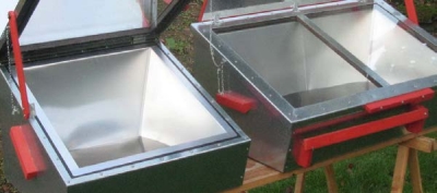
Differences in the cooker Lw:
The assembly of the outer box is basically the same. The few differences are explained in the following section.
3.6
Mounting the box handles
|
|
|
|
Fix the box handles in the same way as the box handles for the Ls (see Clip 3.1). The handles for the Lw are horizontal. |
| |
3.7
Mounting the stay for the glass frame support
|
|
| 1 |
0:00 |
The left block is put into the right hole and vice versa. |
| 2 |
0:18 |
Turn over the front part.
|
| |
- |
Fix the block like the cooker handles, but without a reinforcing plate. (no video clip)
|
| 3 |
0:24 |
The block to which the support will be fixed later (see Clip 8.18)
must be reinforced with a plywood panel in the same way as the cooker handles. Do not use silicone. |
|  |
3.8
Riveting the outer box
|
| 1 |
0:00 |
Fix the outer box of the Lw in the holding device Jig 3.3 which was also used for fixing the box of the Ls (see Clip 3.3). |
| 2 |
0:17 |
When one side part is riveted, move the box on the jig. |
| 3 |
0:57 |
Unlike with the Ls, the second side part is fixed temporarily at first. |
| 4 |
1:26 |
To fix the front part of the box, turn the box and the jig upright. |
| 5 |
1:43 |
Remove the side part that was only screwed on and remove the box from the holding device. |
| 6 |
2:16 |
Replace the side part. |
| |  |
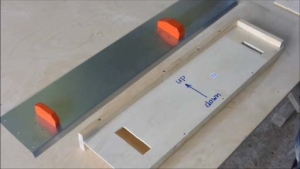
3.9
Reinforcing the rear wall with small metal plates
The glass frame is fixed to the rear wall of the box with hinges. The parts of the rear wall where the hinges will be placed must be reinforced.
|
| 1 |
0:00 |
Place the box on its rear wall on top of a table. |
| 2 |
0:06 |
Apply silicone to the two reinforcement metal plates.
|
| 3 |
0:14 |
Place the two plates on the sides about 50 mm from the edges and place the third plate in the middle.
|
| |  |
3.10
Hint: Removing pop rivets if necessary
Unlike screws, rivets are permanently fixed and cannot be "unriveted".
But with some dexterity, they can be removed if it becomes necessary.
|
| 1 |
0:00 |
Take a drill that is approx. 2 mm wider than the rivet and drill the head of the rivet until it becomes loose. |
| 2 |
0:12 |
Then take a pointy object and push the rivet out of its hole.
|
| |