LAZOLA Construction Manual, Sect. 2
Cutting, drilling and bending the metal parts for the glass frame
2.1
|
The parts of metal glass frames . . .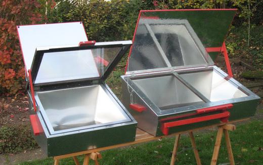
|
are made of galvanized sheet metal 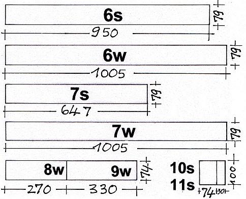 |
2.1.1
|
|
2.1.3
|
|
2.2
|
|
||||||||||||||||||||||||||||||||||||||||||||||||||||
2.2.2
See also the clause Legend after Clip 1.3 |
|
2.2.3
|
| To cut 79 mm wide strips use the positioning Jigs 1.1-10 in order to place the plate on the folding bench. |
||
| - | Once the plate is adjusted, fix the plate, remove the jigs and cut the plate. (no video clip) |
| Use positioning Jigs 1.1-11 to position a 1000 mm plate that is to be cut to a length of 940 mm. |
Important NOTE:
In the meantime a much simpler solution has been found for Jigs 1. The new jigs are adjustable, so less jigs are needed.
| Use a hard steel object to remove the burr that almost always appears at the lower side of a cut. Do this for all edges that will be facing outwards. |
2.3
|
2.3.1
|
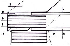
| A cardboard model (of the left side part for the Ls) is used to demonstrate the bending process and to show what the finished part will look like. |
2.3.3
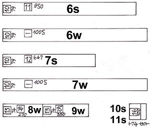
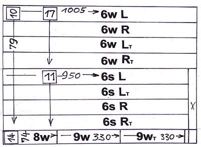
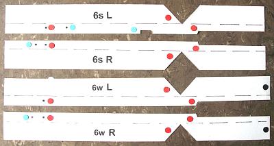
All four side frame parts are largely the same. For all of them:
|
| 1 | 0:00 | 6s L gets an additional hole ahead. |
| 2 | 0:04 | 6s R gets an additional hole further back. |
| 3 | 0:08 | 6w L does not get any additional hole |
| 4 | 0:12 | 6w R gets an additional hole further back (6s R) |
| 5 | 0:16 | Parts 6w L and 6w R are a few inches longer at the front. |
Note: For the cutting of cardboard models of all four parts, there is a copying template in Appendix A1.4 |
2.3.4
|
||||||||||
| 1 | 0:00 | Use a steel nail and Jig 2.1 to copy the marks of the paper template for part 6s L onto the plate that will become the metal template. |
| 2 | 1:40 | Use the punched points to mark what has to be cut out. |
| Note: The template shown in the video is inverted. (See new template) | ||
| Cut out the marked parts of the metal template 6s L T with tin snips |
| Cut out the rectangular notch with a chisel on a steel support. A heavier hammer could be suitable as support. | ||
| - | Use a file to remove all burrs. (no video clip) |
2.3.5 |
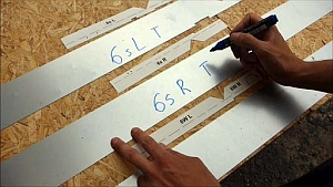
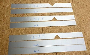
Label the four metal strips provided for the further metal stencils before processing, in order to avoid later confusion. After labeling 6s L T, the video stops. The three further template parts 6s R T, 6w L T and 6w R T are labeled in the same way |
2.3.6
|
| 1 | 0:00 | Place the finished metal template 6s L T on the as far only labeled template 6s R T. (Both are largely mirror-like). |
| 2 | 0:20 | Use the template 6s L T to mark the cut-outs |
| 3 | 0:36 | Transfer all holes (except the "light blue"one) |
| Important note: The rear end of all frame parts must actually touch the side stop of the jig. This was neglected in this clip. The additional holes in three of the four metal templates (light blue) must be marked by means of the paper stencil on which they are marked. |
| Cut out the marked metal template 6s R T. |
2.3.7 |
| 1 | 0:00 | Place the metal template 6s L T on 6w L T. |
| 2 | 0:07 | The front part of the metal template 6w L T is longer than that of 6s L T. Therefore, place the parts with the rear end against the side stop of Jig 2.1. |
| 3 | 0:21 | Transfer the marks of the metal template 6s L T to 6w L T |
| - | Cut out the marked template. (No video clip) |
|
| - | Use the metal template 6s R T in the same way to mark the metal template 6w R T. (No video clip) |
2.4
|
|
 |
|||||
|
2.4.2
Cutting out the side parts of the frame
|
2.5
|
2.5.1
|
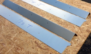
| 1 | 0:00 | Tape the paper template onto the already cut out metal templates 7s and 7w (the video only shows the template 7s, but the 7w is prepared in the same way). |
| 2 | 0:28 | Mark the metal templates. |
| 3 | 0:58 | Connect the punched points using a steel nail. |
| 4 | 1:14 | Cut out the templates. |
2.5.2
|
| 1 | 0:00 | Use metal templates 7s T and 7w T to mark the frame parts. |
| 2 | 0:29 | Drill holes at the punched points through the templates and the underlying frame parts. (see the note after Clip 2.14) |
| 3 | 0:40 | Cut out the parts. |
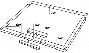
2.6
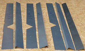
The figure below shows all glass frame parts: |
 |
2.6.1
|
| - | For adjusting the angle of the bench, test with scrap metal plates that have roughly the same length as the parts that have to be bent. Short pieces are bent with the same setting more strongly than long ones. (no video clip) |
|
| 1 | 0:00 | Insert part 6s L into the folding bench (as done before with the cardboard model) with the triangle (not yet cut) on the right hand side. |
| 2 | 0:05 | Turn around part 6s L. The triangle (not yet cut) remains visible at the right hand side for the operator (not visible in the video clip). |
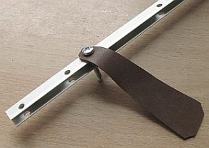
| 3 | 0:17 | Adjust the position of the part, using Jig 2.2 and clamp it. |
| 4 | 0:24 | Now bend the part to 90°. |
| 1 | 0:00 | Insert part 6s R into the folding bench like part 6s L, but with the not yet cut triangle on the left hand side. |
| 2 | 0:20 | Jigs 2.2 are used for the bending of all parts of the frame; this assures that the frame has the same width all around. |
2.6.2
|
| 1 | 0:00 | Insert 6w L in the same way as 6s L and bend. |
| 2 | 0:20 | Insert 6w R in the same way as 6s R and bend. |
2.6.3
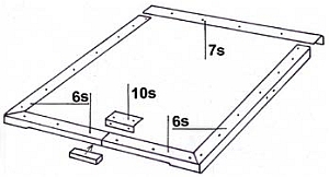
The adjacent picture shows parts 7s and 7w bent and as templates
|
| Insert part 7s in a way that the lateral flanges are hidden while bending. |
2.6.4
|
| Drill holes into the templates. The board on top gives a good hold to the drill. (You will need less force if you drill a 4 mm hole first.) (Parts 8w T, 9w T, 10s T und 11 T need these kinds of holes too.) |
2.7
|
2.7.1
|
| - | Cutting parts 8w and 9w to size from 74 mm wide strips. (No video-clip) | |
| 1 | 0:00 | Transfer the paper template onto part 9w in the usual way. |
| 2 | 0:52 | Drill part 9w together with its punched template 9w T. |
| Place part 9w in such a way, that the side with the holes at its edge is hidden beneath the clamp bar. |
| Bend part 8w from either side. This part has got no holes. |
2.7.2
|
| 1 | 0:00 | Cut parts 10s from a 100 mm plate strip using Jig 2.3a Place a board between the strip and the side stop of the guillotine shears. |
| 2 | 0:25 | Cut parts 11s using Jig 2.3.b (This clip gives an idea of what serial production would look like.) |
2.7.2.2
|
| 1 | 0:00 | Transfer markings from the paper template onto part 10s T using Jig 2.4 Holes must be absolutely parallel with the |
| 2 | 0:30 | Drill 3.5 mm holes into parts 10s and 10s T in one go. |
| 3 | 0:51 | Label the parts. |
| 4 | 1:02 | Bend part 10s like part 9w was bent. |
2.7.2.3
|
| - | Mark and drill part 11s in the same way as before part 10s mark and drill. (no video clip) | |
| 1 | 0:00 | Bend the already drilled part 11s to 90° using Jig 2.5a The drilled side remains visible. |
| 2 | 0:17 | Insert the part already bent with Jig 2.5b and bend it as far as possible. |
| 3 | 0:38 | Finish the second bending by hand and press it flat, using the folding bench. This part will be applied to the reflector support only in sec.8, Clip 8.11 |
2.7.3
In sec. 7, Clip 7.10 , the glass frame hinges are riveted to the back of
the cooker. For greater stability of the back part, reinforcement
plates are attached *, for Ls 2 pieces, for Lw 3 pieces. They are |
Differences in the Cooker Lw:All the special features of the glass frame parts were considered in the previous instructions.The only further difference in the Lw: The stove has a different glass frame support than the L3s, so the angle plate (part 11) is obsolete 2.7.2.3 |