LAZOLA Construction Manual, Sect. 5
Mounting the frame in the outer box and placing the inner box (tub)
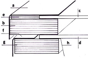
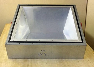
Preliminary remarkThe wooden frame (g) connects inner box (h) and outer box (f). It prevents heat conduction from the inner box to the outer box |
 |
5.1
|
| - | Sand the painted wooden frame using medium grained sandpaper and then remove the dust. (No video clip) | |
| 1 | 0:00 | Place the frame on the stand Jig 5.1. The sloped edge lies at the rear |
| - | Unscrew and remove the front panel of the outer box. (No video clip) | |
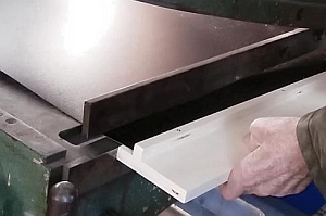
| 2 | 0:14 | Place the outer box onto the Jig for test purposes and place the front panel, too. Check the fit and remove again |
| 3 | 0:26 | Fix the front part again temporarily. Check fitting of the frame and remove the front part again |
5.1.2
|
| 1 | 0:00 | Using Jig 5.2 apply silicone to the frame to all sides except the front |
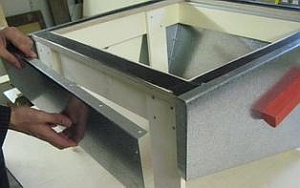
| 2 | 0:22 | Place the outer box on the frame from behind |
| 3 | 0:36 | Fix the front part of the outer box temporarily with woodscrews |
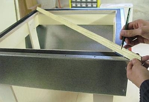
| 4 | 1:16 | Adjust the outer box until it is exactly rectangular by checking crosswise |
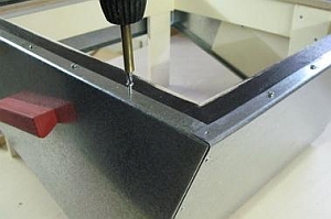
| 5 | 1:59 | Fix the frame with two diagonally positioned woodscrews Nr.8. Depending on how hard the wood is, you may have to prick or drill 2.5 mm holes |
| 6 | 2:36 | Now drill all remaining holes on both sides |
| 7 | 3:01 | Fix all remaining screws. (The corner screws are still missing. The holes are drilled in Clip 5.3) |
5.1.3
|
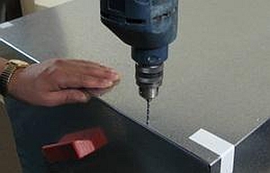
| 1 | 0:00 | Drill 2.5 mm holes through flap of the front panel |
| 2 | 0:14 | Remove the front panel a last time |
| 3 | 0:32 | Remove the outer box with the frame from the stand |
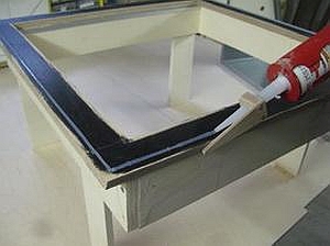
| 4 | 0:40 | Apply silicone to the front side of the frame |
| 5 | 0:55 | Put the front panel back in its position. |
| 6 | 1:08 | Rivet the front panel |
| - | Screw the front panel to the frame. (No video clip) | |
| - | For drilling the 3.5 mm holes in all four corners, use the drill stop Jig 5.4 this is to avoid drilling too deep. (No video clip) | |
| - | Fasten the corner screws (No video clip) |

5.2
By screwing the outer box to the box frame, the outer box is exactly at right angles. The bottoms that have already been cut in Sect. 1,
could now be riveted. However, this may happen only after the insulation has been filled in (sect. 6.2.5).
Nevertheless, the still missing rivet holes in the lower flanges of the side walls are drilled right now.
|
| 1 | 0:00 | Turn the box over and support the front part of the outer box |
| 2 | 0:04 | Bottoms 5s, acc. 5w that have already been prefabricated in chap. 1 are fixed with adhesive tape to the underside of the outer box |
| 3 | 0:30 | Drill 3.2 mm holes in the flanges underneath, using drill stop Jig 5.4 Jig 5.3 takes 3.5 mm drills. Here however this size is too big. Wrap a piece of tape around the 3.2 mm drill |
| 4 | 0:52 | At first, drill two diagonal holes and secure the bottom part with two rivets, which are only inserted, but not riveted. This prevents the bottom part from slipping |
| 5 | 1:08 | Drill all further holes |
| 6 | 1:17 | Mark the bottom and box at one corner and put them aside until they will be used in sect. 6.2.5 |
5.3
Important preliminary note:
|
 |
5.3.1
|
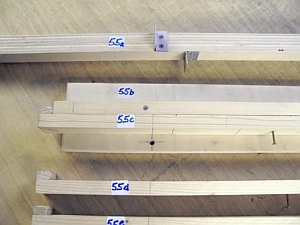
| 1 | 0:00 | Mark the aluminium profiles/strips with Jig 5.4a at three different lengths:
|
||||||||||
| 2 | 0:44 | Cut parts with metal saw Note: For a bigger number of pieces, it is worthwhile to cut the aluminum profiles with an angle grinder. If the aluminum profiles are not available on site, they must be supplied together with the small parts. It will be possible then, to have the various strips cut to size by the supplier. |
||||||||||
| 3 | 1:07 | Finishing the strips at right angles, first align all cuts flush on one side | ||||||||||
| 4 | 2:13 | Then align the second side flush | ||||||||||
| 5 | 2:47 | Remove the burr with fine sanding paper at all ends | ||||||||||
| 6 | 2:58 | Fasten the support board Jig 5.4b to the drill stand | ||||||||||
| 7 | 3:16 | Screw the gauge Jig 5-5c to the support board for drilling the 500 mm strips | ||||||||||
| 8 | 3:31 | Fix all strips with 500 mm length by adhesive tape and drill all 4.2 mm holes | ||||||||||
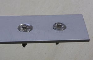
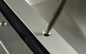
| 9 | 6:29 | A l l e L ö c h e r v e r s e n k e n Important: Use a countersink bit suitable for aluminium and grease it before use, otherwise a disturbing ridge forms around the hole. The countersunk hole must be so deep, that even slightly oblique screws will not protrude. See. fig.: The left hole is countersunk correctly, the right one is not deep enough |
5.3.2
|
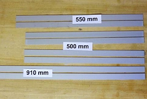
| - | Use tin snips to cut the big board in widths that exceed the length of the strips needed) | |
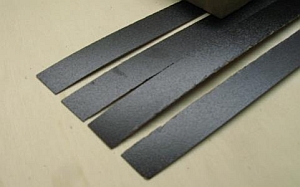
| 1 | 0:00 | Place the cut off pieces into the guillotine shears and cut the strips like cutting sheet metal. Appliance Jig 5.3 helps to position them correctly. |
| 2 | 0:23 | Mark the length of the strips. They are slightly shorter than the aluminium profiles |
| 3 | 0:39 | They can also be stacked and then cut at once |
| 4 | 1:22 | Even more strips can be cut in one go by clamping them as one block in a vice and using a hacksaw |
5.3.3
|
| 1 | 0:00 | Connect the aluminium frame with adhesive tape temporarily |
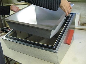
| 2 | 0:28 | Insert the inner box temporarily into the outer box and align laterally by eye. Secure the inner box with adhesive tape |
| 3 | 0:44 | Place the aluminum frame and align it |
| 4 | 1:28 | Check the aluminum frame crosswise and correct if necessary |
| 5 | 1:55 | Insert the lower insulation strip and drill the first 4.2 mm hole to a depth of 4 mm, employing the drill stop Jig 7.5. Mark the insulation strip |
| 6 | 2:27 | Fix the aluminum frame at the top at an angle with adhesive tape and remove the adhesive tape from the upper edge |
| 7 | 2:49 | Insert the insulation strip temporarily and drill the upper hole diagonally to the first hole at the bottom by drilling the second 4.2 mm hole to a depth of 4 mm deep using drill stop Jig 7.5. Mark the insulation strip |
| 8 | 3:22 | Mark the aluminum frame on the upside and remove. Remove the inner tub from the outer box |
5.3.3.2
|
| 1 | 0:00 | Use nozzle guide Jig 5.2 to apply silicone all around the box frame |
| 2 | 0:22 | Align the inner box according to the holes already drilled |
| 3 | 0:42 | Press down the top flaps of the inner box using a wooden strip |
| 4 | 0:58 | Apply silicone to the insulation strips and place them on the flaps of the inner box |
| 5 | 2:06 | Place the aluminum frame on top and adjust it by means of the holes already drilled |
| 6 | 2:39 | Insert screws Nr. 6a into the two holes already drilled |
| 7 | 3:10 | Drill the other holes. If the frame is made of hardwood, start with a 2.5 mm drill. Do not worry about depth, as you will be using thicker screws Important: Drilling must start right in the center of the holes in the aluminium profiles. Pricking them before drilling may be advisable |
| 8 | 3:20 | If the box frame is made of soft plywood, it is sufficient to drill 3.5mm wide holes, but only about 3 mm deep |
| 9 | 3:33 | Important: The screw must be set at a right angle to the aluminium rails, otherwise its head may jut and press against the glass. The screws heads must lie evenly in their sunken holes on the aluminium profiles |
| 10 | 3:46 | Squeezed out silicone is easily removed once it has dried for several hours |
Divergences of Model Lw (double width):In general the steps are very similar to those used for the Ls. However due to the size of the parts, several changes are necessary Regarding 5.1 u. 5.2 |
| 1 | 0:00 | For the following steps use stand Jig 5.1b |
| 2 | 0:03 | Place the box frame on the stand |
| 3 | 0:06 | Put a stop sign on one short side of the frame |
| 4 | 0:09 | Apply silicone to the three remaining sides |
| 5 | 0:12 | Insert the outer box into the frame. Start from the side that has silicone on it. This is a task best managed with a helper |
| 6 | 0:15 | Insert the side panel |
| 7 | 0:18 | Fix the side panel temporarily using woodscrews |
| 8 | 0:21 | Check the box by measuring crosswise |
| 9 | 0:24 | Drill the first hole at the end of a flap of the long sides |
| 10 | 0:27 | Place a screw in the hole |
| 11 | 0:30 | Crosscheck again |
| 12 | 0:33 | Drill a hole diagonally and place the second screw |
| - | Straighten the long flaps using a straight batten and then fix them in the middle with woodscrews. (No video clip) |
Regarding 5.1.3
Removing the outer box from the stand
| 1 | 0:00 | Unscrew the side panel once more for removal |
| 2 | 0:03 | Remove the side panel one last time |
| 3 | 0:06 | Pull the stand out of the outer box |
| 4 | 0:09 | Put the side panel back in its place |
| 5 | 0:12 | Now fix it, this time using rivets |
| 6 | 0:15 | Drill and screw the upper flap |
Regarding 5.2
Preparing the bottom plates for riveting
| - | The bottom parts for the Lw have already been cut to size together with the bottoms for the Ls. (see sec. 1.5.2.2 and Clip 5.4, 1 0:00 - and 2 0:04. Clip 5.4 applies to the Ls as for the Lw) (no video clip) | |
| - | Regarding Clip 5.4, point 6: When the position of the bottom is secured by means of two diagonal holes into which temporarily rivets have been inserted, drill one hole each in the middle of the bottom and secure the bottom temporarily with rivets. Before drilling, fix these spots with adhesive tape. Make sure that the front and back panels protrude equally at the whole length. (no video clip) |
Regarding 5.3.1
Cutting the aluminium profiles, drilling and countersinking the holes
Regarding 5.3.2
Cutting insulation strips with guillotine shears
Parts for the Lw were produced together with those for the Ls. (Clips 5.5 and 5.6)
Regarding 5.3.3
Inserting the inner box, fixing the insulation strips and the aluminium profiles
The steps for the Lw are almost the same as for the Ls.
(see Clips 5.7 and Clip 5.8)
Regarding 5.3.2
Cutting insulation strips with guillotine shears
Parts for the Lw were produced together with those for the Ls. (Clips 5.5 and 5.6)
Regarding 5.3.3
Inserting the inner box, fixing the insulation strips and the aluminium profiles
The steps for the Lw are almost the same as for the Ls. (see Clips 5.7 and Clip 5.8)